4. Measurement equipment
4.1. SWR measurements involving the „Stockton Bridge“
In order to ensure correct coupling the inductive impedance of the transformer must significantly exceed 50 Ω.
For example:
Core RIK20 (blue)
20 turns ≈ 1600 µH ≈ 1 kΩ (@ 100 kHz) ≈ 5 kΩ (@ 500 kHz)
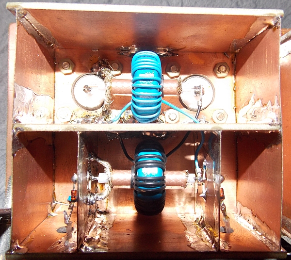
„Stockton-Bridge“ made by DL3ARM
Assembly draft by DL3ARM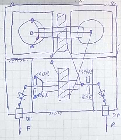
4.2. Resonance indicator
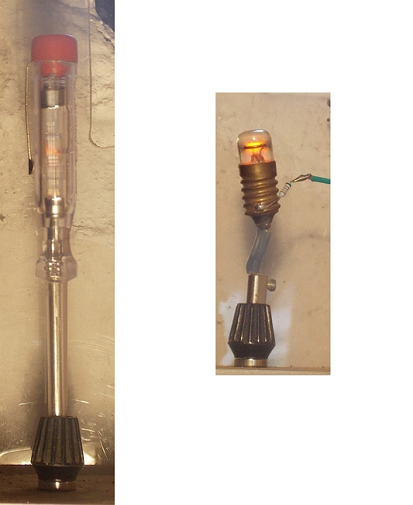
To ensure proper compensation of the reactive part of the antenna impedance, a simple procedure can be applied. Based on the assumption that the antenna is short compared to the wavelength, it represents a capacitive load that is connected in parallel to the variometer coil, which together constitute a parallel resonance circuit. A glow lamp (e.g. a common phasing tester) can be connected between the variometer output and ground. Near resonance a glow can be observed even at low input power of a few watts. By maximizing the glow the antenna matching can be optimized. However a small detuning of the circuit is caused by the additional capacitance of the lamp.
4.3. Measurement of antenna current
Removable current probe made of gripper and ferrite by DL3ARM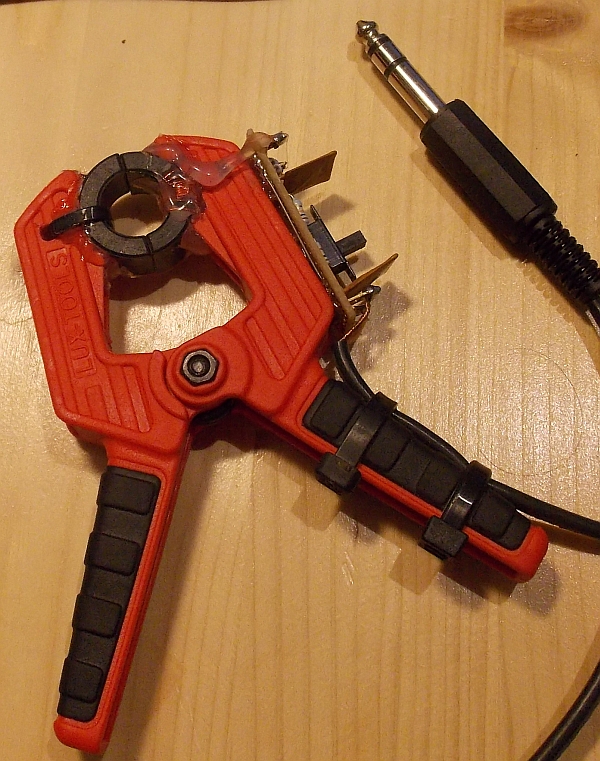
Fixed current probe with a toroid, located in the ground wire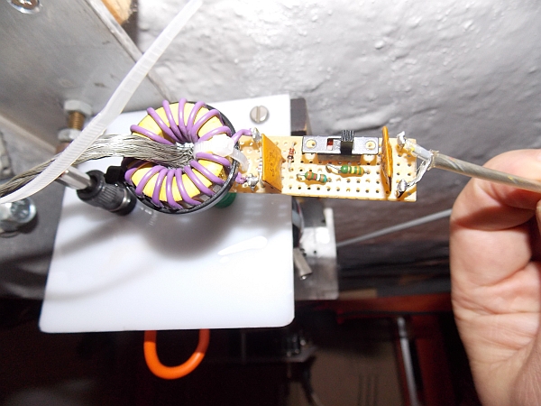
Current probe circuit including equations and an example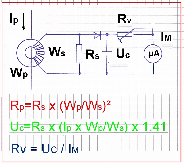
When using a toroid with 10 turns and a 10 Ω secondary resistance, the primary resistance results in 0,1 Ω.
Let’s assume that we use an instrument with full-scale deflection at 100 µA. When connecting a 14,1 kΩ series resistance to it, full-scale is reached for a primary current Ip of 1 A rms (root mean square). That’s in theory. However it is more practical and useful to terminate the RF line with a 50 Ω dummy load and to apply an input power of 50 W which also results in a primary current Ip of 1 A rms. The series resistance can then be adjusted to calibrate the instrument to the desired scale. As an example 100 µA (full-scale) could be assigned to correspond to 50 W. One could also think of assigning 50 µA to correspond to 50 W.
The above calculations base upon the assumption of ideal transformers and diodes. Inaccuracies may stem from the diode characteristic and interwinding capacitance of the transformer.
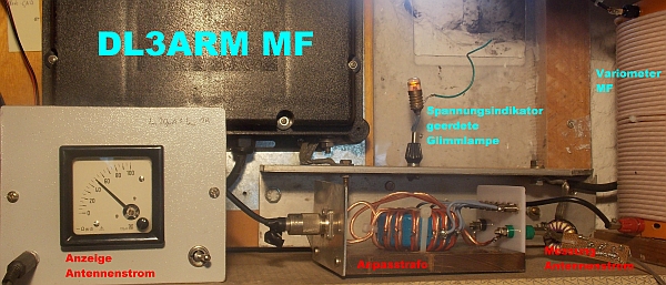
Measurement equipment in operation during MF transmission