Note: The subsequently presented circuits, components and measurement equipment were not optimized. Some were derived from experimental results and actuated under my particular local conditions. A successful reproduction elsewhere cannot be ensured.
1. MF RX DL3ARM
As a receiver the TS570 with additional preamplifier and preselector is employed. The idea of using the mechanical filter type FZ02 arose while designing the receiver for the MF grabber which is now in use at DM4TR. I would like to acknowledge Wolfgang DH1AKF for contributing the following FET circuit:
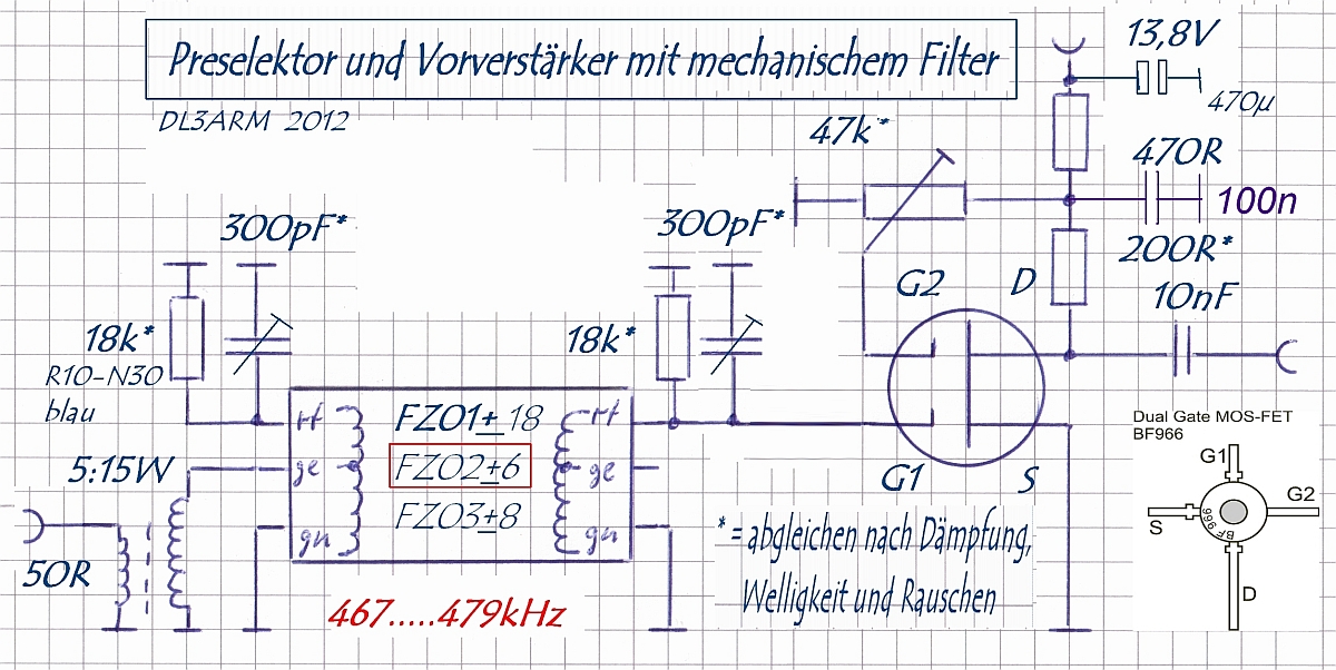
Preselector and preamplifier with mechanical filter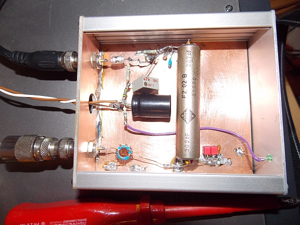
Frequency response of the filter obtained by connecting the SDR-stick “Nano”. By skipping the RF section the signal is directly fed to the ADC inside the stick.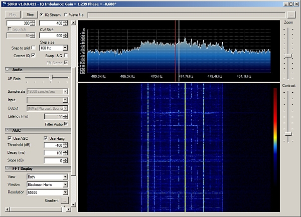
In this configuration the SDR-stick works from 0-1 MHz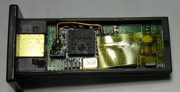
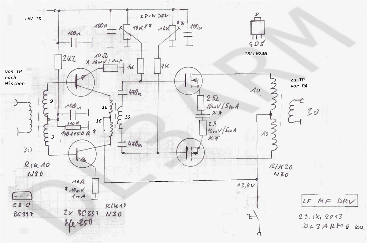
2.1. TX LF / MF DL3ARM "Linear"
The signal generation is performed by the TS570. This offers a variety of modulation standards as well as a variable output power.
Following the ideas of G3XBM, the signal is down-converted to the LF or MF bands respectively and amplified to about 5 W by a linear PA.
![]()
![]()
![]()
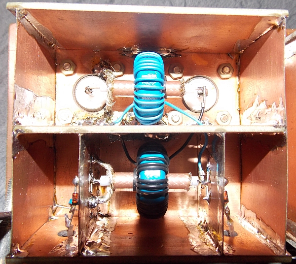
The push-pull class-B power amplifier with 2x IRFP260N ( max. 200V / max. 50A). Operated at a drain supply voltage of 70 V.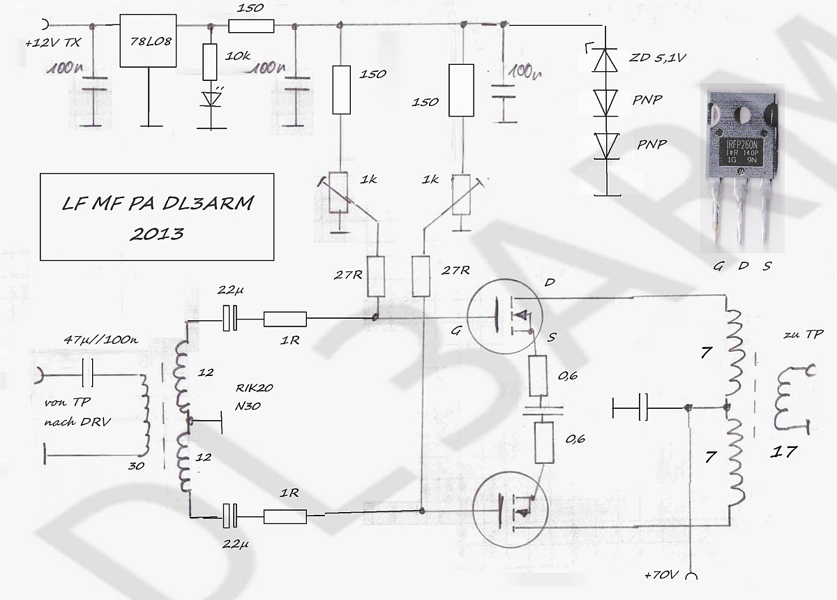
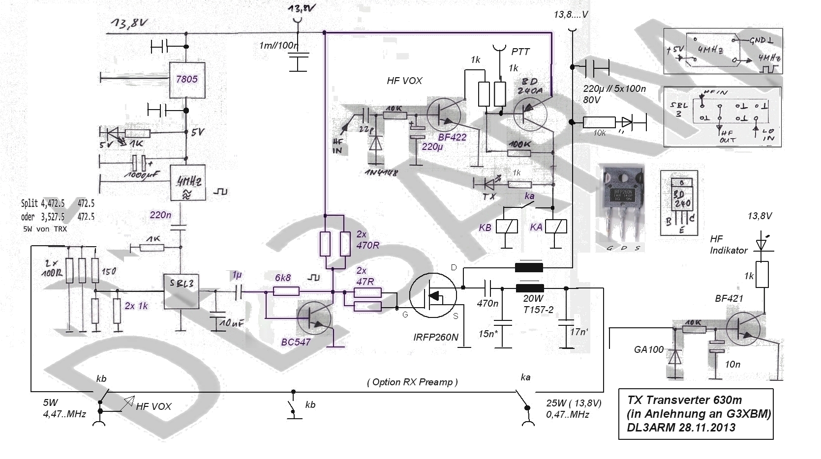
2.2. UFS472,5 ein Sendeumsetzer Kurzwelle / 630m
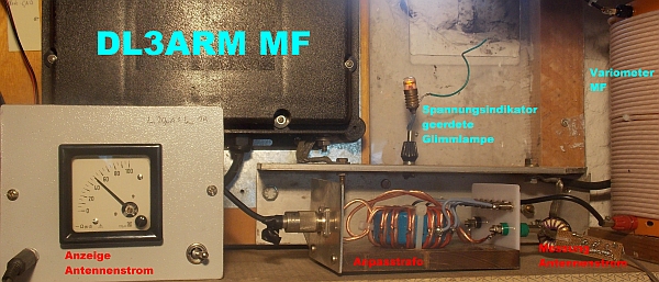
During past electronic projects, transverters were integrated in housings of old UFS radios. Those radios were commonly used by the public authorities in the former German Democratic Republic. Due to positive experience and the still good availability of UFS parts the transverter for the 630 m band was also built inside a UFS housing. The circuit follows this of G3XMB with minor modifications. To improve the sensitivity and selectivity of the receiver, preselector and preamplifier stages were added which required an additional relay for RX / TX switching. As an LO a 4 MHz / 5 V crystal clock oscillator was used. The FET PA received a separate line for its drain voltage supply. Low pass and RF choke elements were implemented on ferrite rings. Preceding the mixer stage an RF VOX was added. The 470 kHz output signal can be monitored by the LED of an RF indicator circuit.
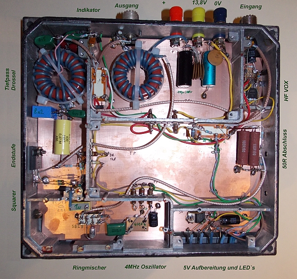
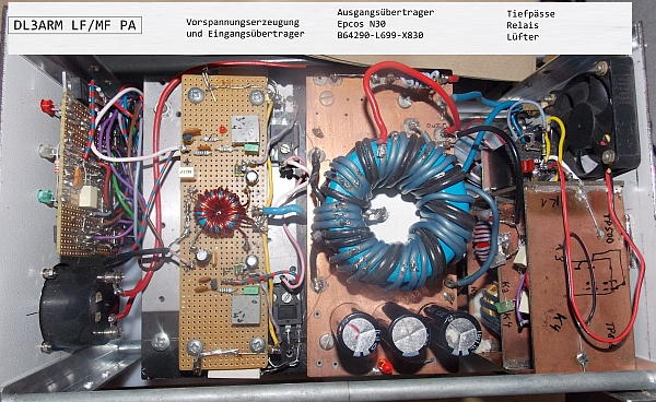
The photo on top displays the 630 m transverter in the UFS housing
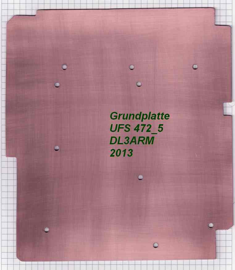
The bottom photo shows the base plate. The second foldaway frame is still empty.
My antenna is at 10 m and extends 32 m in length. This is rather small for MF however I don’t have more space available.
Nevertheless I was able to build quite a striking antenna system.
To achieve a reasonable RF grounding the backyard area is covered with lots of stainless steel wire. Much of it was put under pavement and is invisible year-round. When the backyard is not used during winter time, more wire and wire mesh is added to further improve grounding.
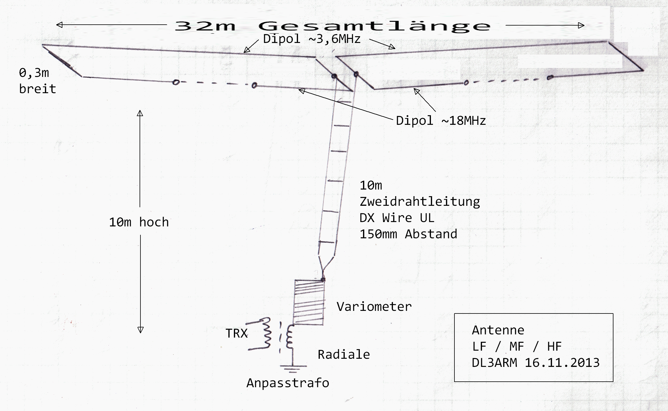
The tuning variometer provides compensation for the reactive part of the antenna load impedance. Its inner coil may rotate continuously and does not require any limit switch or sliding contacts.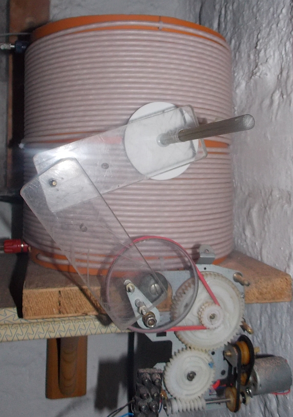
When operating the LF band another coil must be connected in series...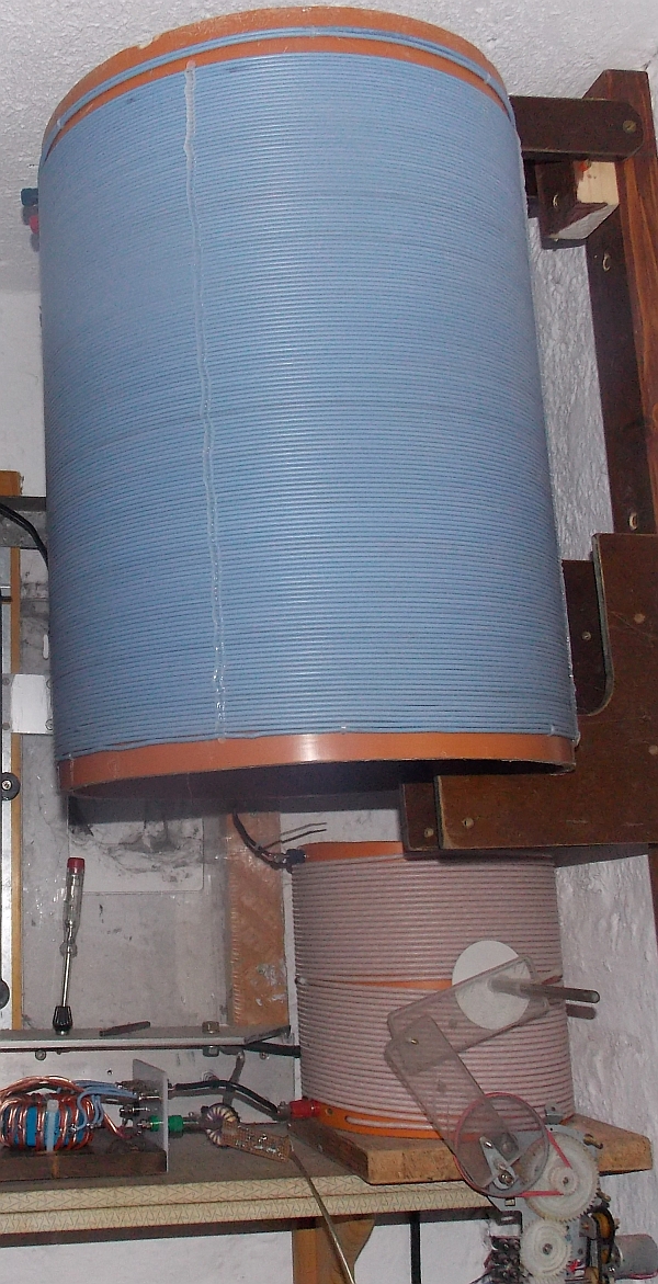
The transformer converts the transmitter output impedance (50 Ω) to the resistive part of the antenna impedance whose reactive part becomes compensated by the variometer. As an alternative not involving a transformer, matching can also be achieved by tapping the grounded coil. However the correct tap usually is not found on a full turn which makes it difficult to localize the correct position and reduces matching accuracy. Moreover it’s a difficult task establishing a tap when hf litz wire is used for the coil.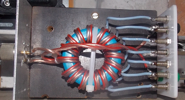
4. Measurement equipment
4.1. SWR measurements involving the „Stockton Bridge“
In order to ensure correct coupling the inductive impedance of the transformer must significantly exceed 50 Ω.
For example:
Core RIK20 (blue)
20 turns ≈ 1600 µH ≈ 1 kΩ (@ 100 kHz) ≈ 5 kΩ (@ 500 kHz)
„Stockton-Bridge“ made by DL3ARM
Assembly draft by DL3ARM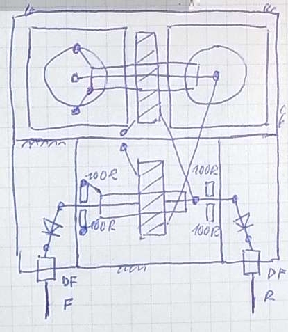
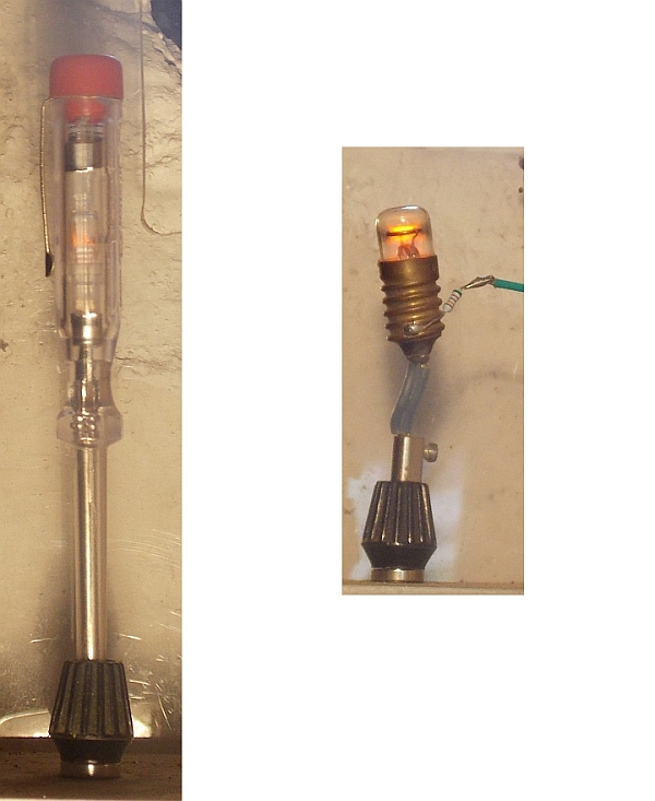
4.2. Resonance indicator
To ensure proper compensation of the reactive part of the antenna impedance, a simple procedure can be applied. Based on the assumption that the antenna is short compared to the wavelength, it represents a capacitive load that is connected in parallel to the variometer coil, which together constitute a parallel resonance circuit. A glow lamp (e.g. a common phasing tester) can be connected between the variometer output and ground. Near resonance a glow can be observed even at low input power of a few watts. By maximizing the glow the antenna matching can be optimized. However a small detuning of the circuit is caused by the additional capacitance of the lamp.
4.3. Measurement of antenna current
Removable current probe made of gripper and ferrite by DL3ARM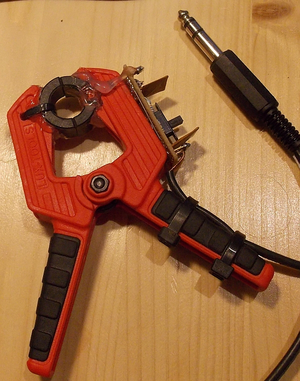
Fixed current probe with a toroid, located in the ground wire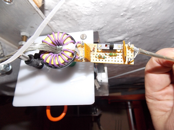
Current probe circuit including equations and an example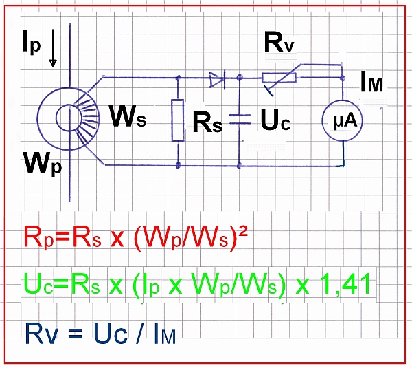
When using a toroid with 10 turns and a 10 Ω secondary resistance, the primary resistance results in 0,1 Ω.
Let’s assume that we use an instrument with full-scale deflection at 100 µA. When connecting a 14,1 kΩ series resistance to it, full-scale is reached for a primary current Ip of 1 A rms (root mean square). That’s in theory. However it is more practical and useful to terminate the RF line with a 50 Ω dummy load and to apply an input power of 50 W which also results in a primary current Ip of 1 A rms. The series resistance can then be adjusted to calibrate the instrument to the desired scale. As an example 100 µA (full-scale) could be assigned to correspond to 50 W. One could also think of assigning 50 µA to correspond to 50 W.
The above calculations base upon the assumption of ideal transformers and diodes. Inaccuracies may stem from the diode characteristic and interwinding capacitance of the transformer.
Measurement equipment in operation during MF transmission